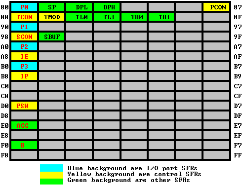
Special function registers are upper RAM memory in the 8051 microcontrollers. These registers contain all peripheral related registers like P0, P1, P2, P3, timers or counters, serial port and interrupts-related registers. The SFR memory address starts from 80h to FFh. The SFR register is implemented by bit-address registers and byte-address registers.
The accumulator and B registers and port registers all are bit addressable register remaining all are bye addressable registers.
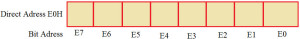
Accumulator: The accumulator which is also known as ACC or A is a bit as well as a byte-addressable register by an address of the accumulator. If you want to use a bit-addressable register, you can use a single bit (E0) of the register and you can use an 8-bit of the accumulator as a byte-addressable register. The accumulator holds the results of most Arithmetic and logical operations.
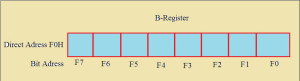
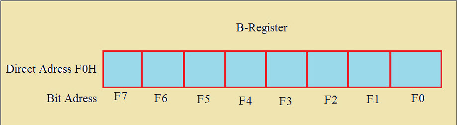
B-Register
The B-register is a bit and byte-addressable register. You can access 1-bit or all 8-bits by a physical address F0h. Suppose to access a bit 1, we have to use f1. The B register is only used for multiplication and division operations.
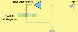
Port Registers
The 8051 microcontroller consists of 4-input and output ports (P0, P1, P2, and P3) or 32-I/O pins. Each pin is designed with a transistor and P registers. The pin configuration is very important for a microcontroller that depends on the logic states of the registers. The pin configuration as input given by 1 or output 0 depends on the logic states. If logic 1 is applied to the bit of the P register, the output transistor switches off the appropriate pin that acts as an input pin.
Counters and registers:
Many microcontrollers consist of one or more timers and counters. The timers are used to generate precious time delay and the source for the timers is a crystal oscillator. The counters are used to count the number of external events – for instance, the objective counter, and the source for counters are external pulses applied across the counter pin.
The 8051 microcontroller consists of two 16-bit timers and counters such as timer 0 and timer 1. Both the timers consist of a 16-bit register in which the lower byte is stored in the TL and the higher byte is stored in the TH. The Timer can be used as a counter as well as for timing operation that depends on the source of the clock pulses to the counters.
The Counters and Timers in 8051 microcontrollers contain two special function registers: TMOD (Timer Mode Register) and TCON (Timer Control Register), which are used for activating and configuring timers and counters.
The Data Pointer (DPTR) is the 8051s only user-accessable 16-bit (2-byte) register. The Accumulator, "R" registers, and "B" register are all 1-byte values. DPTR, as the name suggests, is used to point to data. It is used by a number of commands which allow the 8051 to access external memory. When the 8051 accesses external memory it will access external memory at the address indicated by DPTR. While DPTR is most often used to point to data in external memory, many programmers often take advantge of the fact that its the only true 16-bit register available. It is often used to store 2-byte values which have nothing to do with memory locations. It consists of one 8-bit register for DPL and other 8-bit register for DPH.
Serial Transmission Modes Serial data can be transferred in two modes – asynchronous and synchronous. Asynchronous Data Transfer: Data Transfer is called Asynchronous when data bits are not “synchronized” with a clock line, i.e. there is no clock line at all! Let's take an analogy. Imagine you are playing a game with your friend where you have to throw coloured balls (let’s say we have only two colours – red (R) and yellow (Y)). Let's assume you have an unlimited number of balls. You have to throw a combination of these coloured balls to your friend. So you start throwing the balls. You throw R, then R, then Y, then R again and so on. So you start your sequence RRYR… and then you end your round and start another round. How will your buddy on the other side know that you have finished sending him the first round of balls and that you are already sending him the second round of balls?? He/she will be completely lost! How nice it would be if you both sit together and f...
The 8051 is organized so that data memory and program code memory can be in two entirely different physical memory entities. Each has the same address ranges. The structure of the internal RAM has been discussed previously. A corresponding block of internal program code contained in an internal ROM occupies code address space 0000h to FFFFh. The program addresses higher than 0FFFh, which exceed the internal ROM capacity, will cause the 8051 to automatically fetch code bytes from external program memory. Code bytes can also be fetched exclusively from an external memory, addresses 0000h to FFFFh, by connecting the external access pin to ground. The PC doesn't care where the code is the circuit designer decides whether the code is found totally in internal ROM, totally in external ROM, or in a combination of internal and external ROM. NAME FUNCTION ...


Comments
Post a Comment