Pin description of Microcontroller
Obviously, each and every component pin description and connection is very important to come to the hardware execution.
Today's podcast about microcontroller pin description. Most probably, the most emerging microcontroller chip is Atmel manufactured microcontrollers, too many microcontrollers are there. We will talk about 8051 family microcontroller.
In this 8051 family microcontroller, vivid microcontroller types, in that most using one AT89S52 MC. A glimpse of pins of AT89S52 below,
Total in this DIP microcontroller type AT89S52 40 pins. 4 I/P ports, each port contain 8 pins, so total 32 input and output pins. left with 8 pins.
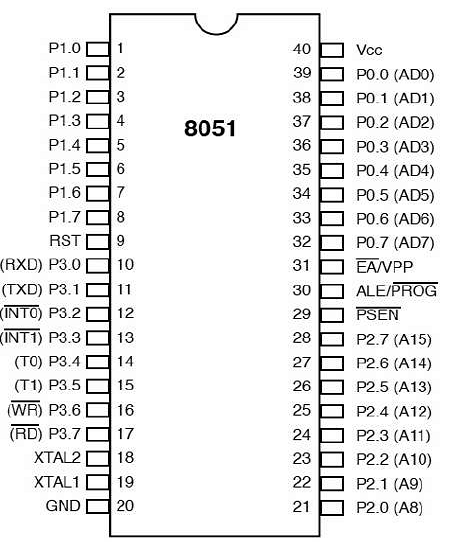
Pin Diagram:
I thought you got a clear idea about the pin diagram, I will a perfect usage of each pin.
Pin Description:
- Pins 1 to 8 − These pins are known as Port 1. This port doesn’t serve any other functions. It is internally pulled up, bi-directional I/O port.
- Pin 9 − It is a RESET pin, which is used to reset the microcontroller to its initial values.
- Pins 10 to 17 − These pins are known as Port 3. This port serves some functions like interrupts, timer input, control signals, serial communication signals RxD and TxD, etc.
- Pins 18 & 19 − These pins are used for interfacing an external crystal to get the system clock.
- Pin 20 − This pin provides the power supply to the circuit.
- Pins 21 to 28 − These pins are known as Port 2. It serves as I/O port. Higher order address bus signals are also multiplexed using this port.
- Pin 29 − This is PSEN pin which stands for Program Store Enable. It is used to read a signal from the external program memory.
- Pin 30 − This is EA pin which stands for External Access input. It is used to enable/disable the external memory interfacing.
- Pin 31 − This is ALE pin which stands for Address Latch Enable. It is used to demultiplex the address-data signal of a port.
- Pins 32 to 39 − These pins are known as Port 0. It serves as I/O port. Lower order address and data bus signals are multiplexed using this port.
- Pin 40 − This pin is used to provide power supply to the circuit.
These are the pins are clearly explained, I hope this will help you to better understand.


Comments
Post a Comment